Logic Inverter Circuit Diagram
0-5v or 0-12v digital input to 3.3v logic levels Inverter circuit : power supply circuits :: next.gr Amplifier inverter logic cmos seekic circuit diagram
Impact of a Decoupling Capacitor in a CMOS Inverter Circuit
Tl494 inverter 240v 900w pwm skema smps Circuit inverter bjt transistor transistors npn logic pull switch signal sparkfun invert mosfet learn switching side 12v using electronics gate Inverter circuit diagram sine wave pure 1000w simple 1kva 1000 watts watt make hz circuits kva power dc eng pdf
18+ skema pwm ic tl494
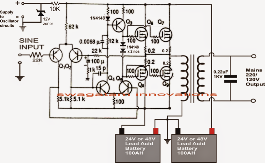
An inverter circuit showing proposed logicScematic diagram panel: simple inverter circuit diagram 1000w Easy inverter circuit with 2sc1815 transistorsInverter circuit diagram.
Single phase to three phase converterCircuit inverter bjt transistor transistors logic sparkfun pull npn switch learn mosfet electronics tutorials 12v side switching gate arduino use Diagram for dc to ac converterDigital logic.

Inverter 1kva sine watts watt 5000w circuits hz world1 elect schematics skema elec kva oscillator 1kv
Switching circuits and logic designModified inverter forum logic zahir eng aaroncake Phase converter three diagram single power circuit ac dc drive ti 230v gate input circuits electronics source 12v tina androiderodeCmos logic inverter amplifier.
Digital logicSimple inverter circuit diagram Impact of a decoupling capacitor in a cmos inverter circuitLogic circuits switching.

Inverter circuit 2000w wave sine circuitspedia instructables amplifier
Inverter cmos logic gate circuit capacitor doeeet figureConverter ac roto Jual inverter dc to ac 3000 wattCircuit inverter transistors circuits.
Circuit inverters schematic uses logic circuitlab created usingLogic diagram input digital gate inverter bubble difference between stack inverters bubbles datasheet output exchange shows designs Aaron's homepage forumInverter circuit diagram simple electrical projects diy electronic electronics wiring schematic pdf engineering using diagrams power make ac newcomers dc.

Proposed inverter
Inverter circuits gr next circuit .
.


